http://www.ti.com/general/docs/suppproductinfo.tsp?distId=26&gotoUrl=https%3A%2F%2Fwww.ti.com%2Flit%2Fpdf%2Fsluucq1″>View Datasheet

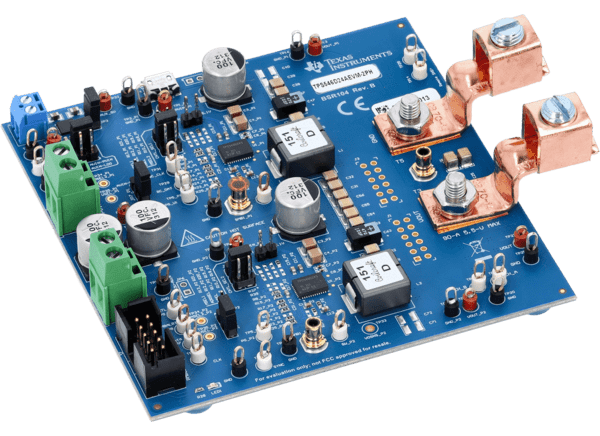
Texas Instruments TPS546D24SEVM-2PH Converter Evaluation Module

Texas Instruments TPS546D24SEVM-2PH Converter Evaluation Module (EVM) is a 2-phase buck converter with two TPS546D24S devices providing a single 0.8V output. The TPS546D24A device is a stackable synchronous buck converter with a PMBus interface that can operate from a nominal 2.95V to 16V input supply. The device allows programming and monitoring via the PMBus® interface with a user-configurable write lock feature for improved security. The Texas Instruments TPS546D24SEVM-2PH is designed to demonstrate the stacking operation of the TPS546D24S in a two-phase, low-output voltage application while providing several test points to evaluate the performance of the devices.
Features

  • The output voltage is marginable and trimmable using the PMBus interface
    • Programmable UVLO, soft start, and enable through the PMBus interface
    • Programmable overcurrent warning and fault limits and programmable response to faults via the PMBus interface
    • Programmable overvoltage and undervoltage warning and fault limits and programmable response to faults via the PMBus interface
    • Programmable turn-on and turn-off delays
  • Regulated 0.8V output up to 80ADC steady-state output current
  • Convenient test points for probing critical waveforms

Required Equipment

  • Voltage Source
    • The input voltage source VIN must be a 0V to 20V variable DC source capable of supplying a minimum of 16ADC to support 80A load with 5V input
  • Multimeters
    • It is recommended to use two separate multimeters: one meter to measure VIN and the other to measure VOUT
  • Output Load
    • It is recommended to use a variable electronic load for the test setup
    • To test the full load current this evaluation module supports, the load must be capable of sinking at least 80A
  • Oscilloscope
    • When using an oscilloscope to measure the switching node voltage or voltage ripple, measure using a Tip-and-Barrel method
  • Fan
    • During prolonged operation at high loads, it can be necessary to provide forced air cooling with a small fan aimed at the evaluation module
    • Maintain the surface temperature of the devices on the evaluation module below the device’s rated temperature
  • USB-to-GPIO Interface Adapter
    • A communications adapter is required between the evaluation module and the host computer
    • This evaluation module is designed to use TI’s USB-to-GPIO or USB-to-GPIO2 Adapter
  • Recommended Wire Gauge
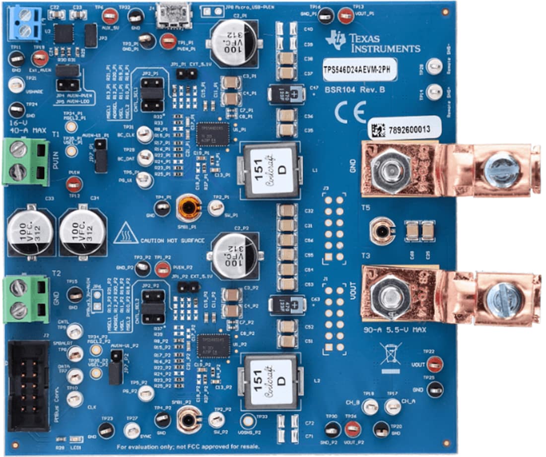
    • Input VIN and GND to T1 and T2 (GND) (12V input) – The recommended wire size is AWG #12, with the total length of wire less than 2 feet (1-foot input, 1-foot return)
    • Output T3 and GND T5 (0.8V output) – The minimum recommended wire size is AWG #10, with the total length of wire less than 2 feet (1-foot output, 1-foot return)
    • A thicker wire gauge can be required to minimize the voltage drop in the wires

Board Layout

Mechanical Drawing - Texas Instruments TPS546D24SEVM-2PH Converter Evaluation Module

Texas Instruments TPS546D24SEVM-2PH Converter Evaluation Module