- support@husseinkey.com
- livechat
http://www.ti.com/general/docs/suppproductinfo.tsp?distId=26&gotoUrl=http%3A%2F%2Fwww.ti.com%2Flit%2Fug%2Fsnvu680%2Fsnvu680.pdf%3Fts%3D1588694013704″>View Datasheet
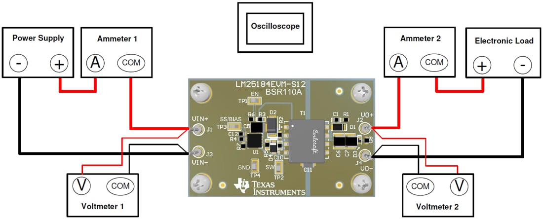
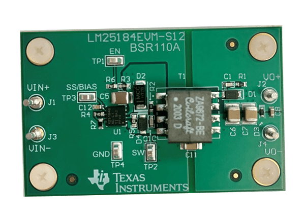
Texas Instruments LM25184EVM-S12 Converter Evaluation Module (EVM) is designed to showcase the performance of the LM25184-Q1 PSR flyback converter with a wide input voltage range. The design is packaged in a miniature footprint with a low component count. It operates over a wide input voltage range of 6V to 42V to deliver a fixed 12V output with better than 1.5% setpoint accuracy and currents up to 1A. The Texas Instruments LM25184-Q1 operates without an auxiliary winding or optocoupler and provides very tight output voltage regulation, better than 1%. The LM25184-Q1 offers a full suite of protection features to ensure the protection of the regulator during fault conditions. These include undervoltage lockout (UVLO) to ensure proper operation during voltage-sag conditions, programmable soft-start (SS) to reduce inrush current, hiccup-mode overcurrent protection (OCP) and thermal shutdown. A precision enable (EN), and output voltage thermal compensation (TC) features are also provided.


