- support@husseinkey.com
- livechat
Infineon Residential Storage Solutions (ESS) offer a wide variety of products to create and manage resilient energy infrastructures at an optimal cost. ESS offers two primary use cases. The first is creating utility-independent, solar-powered homes (residential ESS). On a larger scale, the second use case is utility supplementing generated power during periods of high demand (utility-scale ESS).
Older generation residential solar energy systems are tied to the utility power grid via inverters, which convert power from solar panels to AC electrical power during daylight hours. Marketable excess power might be sold back to utility companies. However, during the hours of darkness, the end-user is relying on the utility’s electricity supply. Utility companies are aware of these limitations and adjust their pricing models accordingly. Residential customers pay based on “time-of-use” rates, which are higher when solar power is not available.
Behind-the-meter ESS is utilized at this point. The electricity that is collected via solar panels charges batteries, the energy is then stored. When using these batteries with an inverter, the demand for AC power can be fulfilled at any time.
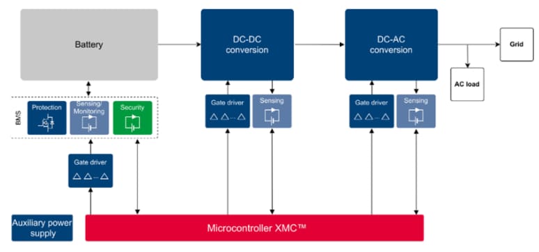
With the increasing number of battery variants and different ESS versions, engineers and designers are constantly confronted with the need for higher efficiency, power density, and reliability in their system designs. Three trends are foreseen that will have a significant impact on how ESS designs will develop and how they will look in the future.
Silicon carbide (SiC) technologies
• Lower cost per watt
• Smaller size and weight of systems
• Enables higher frequencies
• Smaller magnetics
• Fewer losses and better thermals (smaller heatsink)
• High power density
• Simplified bidirectional topologies
• Higher efficiency
• Less bill of materials (BOM) content
• Robustness and higher system reliability
Multi-modular approach
• Reuse of increasing number of 2nd life batteries
• Battery pack connected to its own bidirectional power converter
• Output of converters connected in series to create high voltage DC bus
• Current drawn from a battery does not need to be equal
• Voltage output is controllable
• More flexibility
Battery management systems (BMS)
• Battery protection
• Battery monitoring
• Wider safe operating area (SOA)
• Short circuit protection with higher peak current rates
• Turn-on and turn-off solutions tailored to application needs
• Cheaper solutions with a more compact BOM and more effective parallelization solutions
Infineon’s renowned technical expertise and broad product portfolio for leading-edge ESS solutions ensure reduced design efforts, improved system performance, fast time to market, and optimized system costs.


For residential ESS, the two main system-coupling topologies, which usually come along with PV installations, are the DC-coupled and the AC-coupled.
In a DC-coupled system, the energy stored in the battery is boosted to a specific DC-bus voltage, usually in the range of 400V. This system is directly connected to the DC line using a DC/DC converter, not converting DC to AC.
In the AC-coupled system, the stored energy from the battery is supplied directly into the AC grid. In this case, both a DC/DC converter and an AC/DC inverter are used.
Both systems must be capable of bidirectional operation, drawing energy from the battery and charging the battery with excessively produced power.
Infineon’s latest addition to its SiC portfolio, the CoolSiC™ MOSFET 650V family, is the product of a state-of-the-art trench semiconductor process, optimized to allow no compromises in achieving both the lowest losses in the application and the highest reliability in operation. While leveraging the strong material characteristics of silicon carbide, Infineon’s experts managed to add unique features that increase the device performance, robustness, and ease of use.
When comparing the newly launched CoolSiC trench MOSFET 650V portfolio with the few alternatives currently available on the market, engineers will find convincing reasons for choosing Infineon as their supplier.
Key Features
• Low capacitances
• Optimizing switching behavior at higher currents
• Commutation-robust, fast body diode with low reverse recovery charge (Qrr)
• Superior gate-oxide reliability
• Excellent thermal conductivity and behavior
• Advanced avalanche ruggedness and short circuit capabilities
• Compatibility with standard drivers
• 0V turn-off VGS and wide VGS range
Explaining the value created to users is simple: the new portfolio represents an easy (integration, design-in, use) and cost-effective way to reach top efficiency/density levels when one would instead expect increasing system complexity.
The mentioned trench concept ensures product optimization, fully leveraging the strong material properties of silicon carbide. Engineers will achieve top performance with compact and reliable systems. With Infineon’s CoolSiC, technology systems are constructed with fewer components and reduced magnetics/heatsinks. Consequently, they become simpler, smaller, and cost less.
Performance is crucial, and CoolSiC lives up to it by delivering superior conduction and switching efficiency. Besides performance, some technological features characterizing the CoolSiC trench MOSFET 650V family differentiate them from the competition.
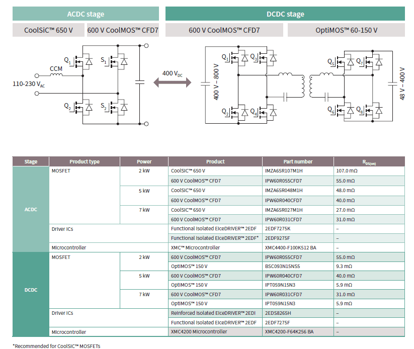

View AC/DC Solution Products
View DC/DC Solution Products
Power Levels
Power levels in industrial ESS range from 10kW to 100kW, and in utility-scale ESS, they exceed 100kW, which are connected to three-phase AC typically at 480VRMS. The system concept is similar to the residential ESS; however, many Li-ion battery packs are connected. Each battery pack comes with its own integrated BMS to produce a total battery voltage higher than 740V.
• 10kW to 100kW industrial ESS
• 100kW utility-scale ESS connected to three-phase AC typically at 480VRMS
2nd Life of Batteries
In times of increasing popularity of e-mobility solutions (particularly electric cars), it can be expected that the world will have to cope with a significant number of used EV-batteries in the future. A considerable advantage of modularly cascaded, multilevel architectures is the ability to enable the 2nd life of batteries – applicable, for example, to batteries that have reached the end of their lifecycle and cannot be used in EVs any longer.
• Modularly cascaded, multilevel architectures
Limitations Caused by using IGBT Discretes and Modules
Traditional systems require 1200V-rated switches (usually IGBT discrete devices and modules) for the power conversion stages that are connected to an 800V to 900V DC-bus voltage. This system architecture, however, does not provide optimal battery utilization. Having battery packs with different states of charge (SOC) connected in series, this system can only operate until one pack reaches the minimum allowable charge level. At this point, the whole system is shutting down, even though other packs may still be sufficiently charged. In short, battery utilization is limited to the weakest battery pack.
• Battery packs with different states of charge (SOC) connected in series
Multi-Modular Approach for Optimal Battery Utilization
To overcome this limitation, modularly cascaded, multilevel architectures that utilize the benefit of highly efficient, low voltage MOSFETs like Infineon’s market-leading OptiMOS™ family have been developed. Each battery pack is connected to its own bi-directional power converter, and the outputs of these converters are then connected in series to create the high voltage DC-bus. By doing so, an equal current can be supplied from the outputs of each of these stages. The current drawn from each battery, to the contrary, must not be equal. The voltage output for each stage becomes controllable. It is possible to bypass stages should their battery state of charge (SOC) drop below the minimum level. With this added flexibility, advanced control schemes are now possible to balance the SOC of different batteries among all the packs by placing a more massive load on those packs with higher SOC.
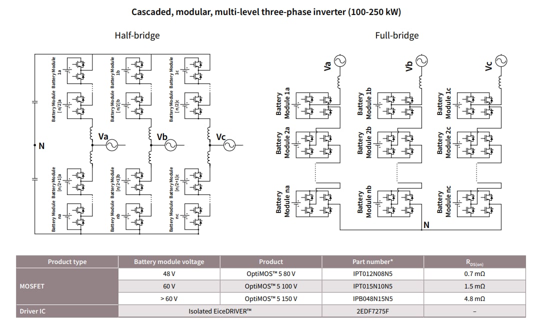

View Multi-Modular Solution Products
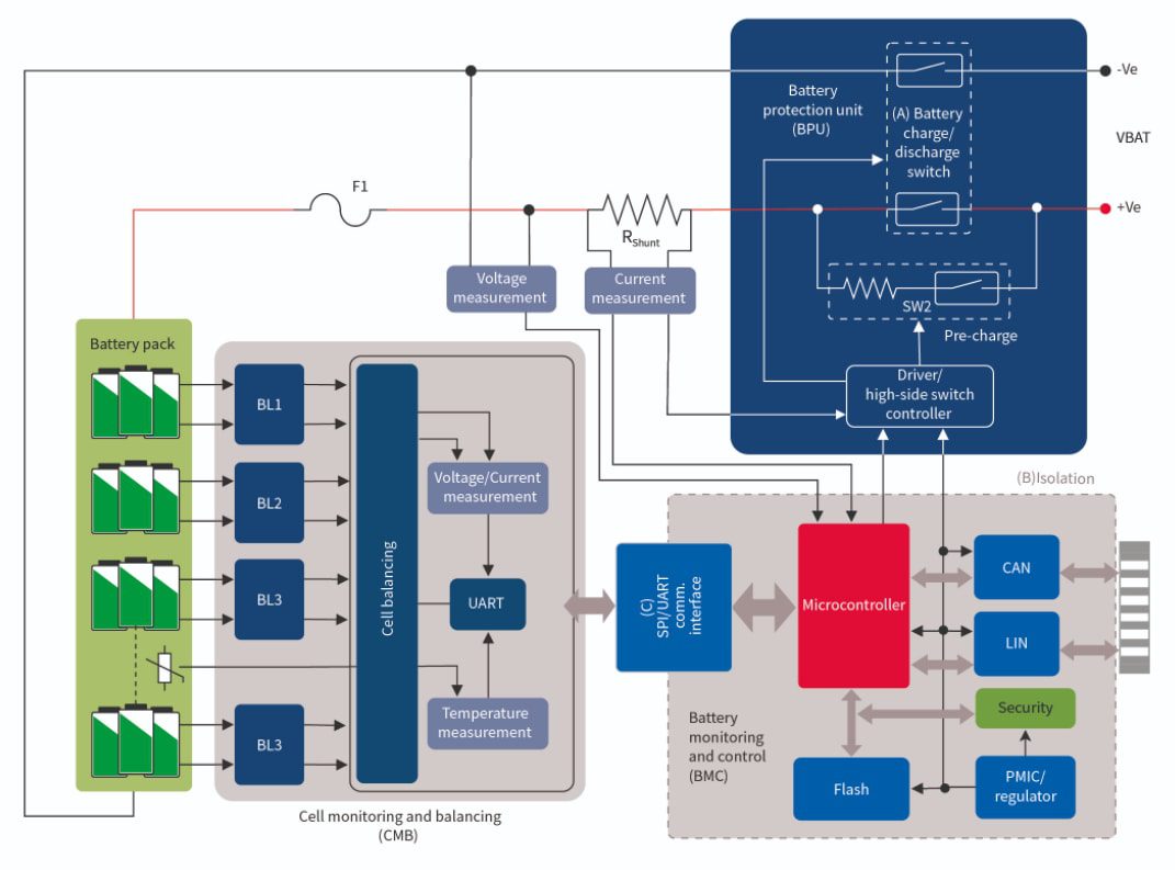
In ESS, a battery management system fulfills two main functions, namely battery protection and battery monitoring.
Battery Protection
Detecting a variety of fault conditions and protecting the battery from damage during the charging and discharging process is the main purpose and functionality of a BMS. Operating a battery outside of its specifications causes damage to the battery cells and leads to battery failure, producing maintenance efforts, and significant cost impact. Batteries must be closely monitored during charging and discharging to avoid these negative effects.
Protection must be provided against:
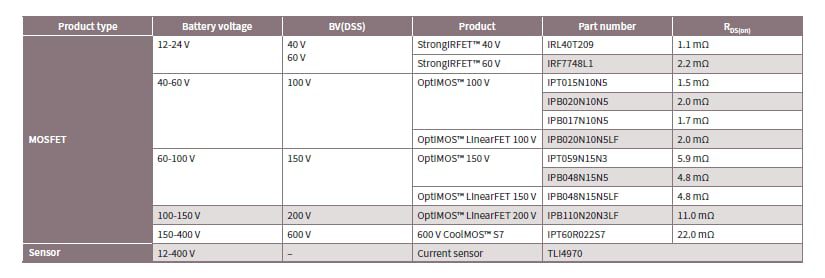
Those designing with Infineon’s solutions will benefit from:
Battery Monitoring
A battery must be monitored systematically, to protect it. The battery management system is in charge of monitoring each of the cells in a battery pack and ensures that they are operated within the safe operating range. Various parameters, such as cell voltage, SOC, state of health (SOH), and the temperature, have a decisive impact on the performance, safety, and lifetime of batteries. A battery needs to be protected against possible external faults that would put the system in danger. Protecting the battery from damage during the normal function of the system (charging and discharging process) is one of the main functionalities of a BMS. Within Infineon’s product portfolio, designers will find the right devices to disconnect the battery system in case a fault is detected, thereby protecting its value. They will also help to detect system faults like overcurrents and short circuits.


View Battery Protection Solution Products


View Battery Monitoring Solution Products
Infineon Power and Sensing Selection Guide


