- support@husseinkey.com
- livechat
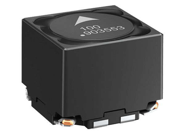
EPCOS / TDK Coupled Inductors are designed for use in a diverse range of applications. These compact coupled inductors feature a high saturation current. The modules can be used as coupled inductors in non-isolated DC/DC converter topologies or as transformers in flyback converters. They can also be used as common-mode inductors in power supply lines. EPCOS / TDK Coupled Inductors provide coupling factors up to 99%. The compact robust designs offer functional isolation voltages between the two windings up to 500V.

The following is an overview of five types of DC/DC converter topologies.
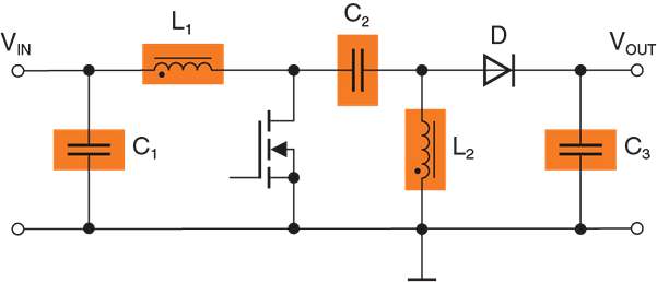

A single-ended primary inductance converter (SEPIC) is ideally suitable for battery-powered devices and automotive applications. These converters provide a constant non-inverted output voltage that can be higher or lower than the input voltage, allowing battery voltage fluctuations and different load scenarios to be compensated. This is possible because the SEPIC technology combines a buck and boost converter. Another benefit of this circuit topology is a constant input current that, in combination with the input filter consisting of C1 and L1, results in a significantly lower conducted interference. Using a coupled inductor can reduce ripple current load and core losses. Although the coupling capacitor C2 offers some isolation between input and output, SEPIC is one of the non-isolated topologies.
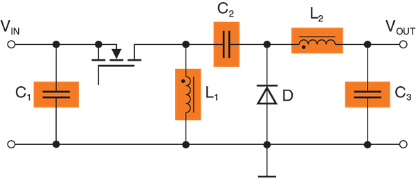

ZETA is a multi-winding converter topology that basically provides similar functionality to SEPIC. Both power converters can step up and down the input voltage and generate a stable non-inverting output voltage. Another commonality is the DC transfer function VOUT = VIN x D/(1-D). Due to the slightly rearranged circuit configuration with L2 and C3 at the output, ZETA converters offer a continuous output current with a low ripple. Unlike a real buck-boost, ZETA converters require only one buck controller IC directly driving a MOSFET. The output is not isolated from the input.
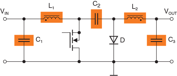

Like SEPIC and ZETA topologies, Ćuk converters can regulate a voltage that is above or below the input voltage. A special feature, needed by some applications, is an inverted output voltage. Another advantage, from an EMI point-of-view, is a continuous current flow in combination with LC filters on both the input and output sides of the converter. This provides a stable current drain from the battery while greatly minimizing the ripple current. The output is not isolated from the input.
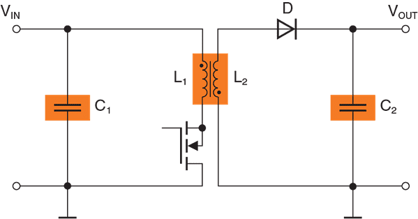

Flyback converters are one of the most commonly used topologies in industrial electronics and lower power automotive applications. These converters offer a relatively simple and cost-effective design of this circuit topology, which needs only a few components. The coupled inductor serves as a storage choke and also offers galvanic isolation between input and output. The energy transfer occurs during the off-time of the MOSFET. The topology can generate non-inverted output voltages far below or above the input voltage. Depending on the converter’s isolation requirements or the application’s safety standards, either a transformer or a coupled inductor with functional isolation of up to 500V can be used. Flyback converters also provide the ability to generate multiple output voltages. The downsides of this topology are high voltage peaks generated by the switching transistor. An EMC filter may be necessary at the converter’s input to suppress this conducted interference.
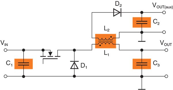

Coupled inductors also can be utilized to create an auxiliary or a second output voltage, respectively, by using just a single buck regulator. This can help to simplify the complexity of the circuits, saving costs and board space.
What is a coupled inductor?
Inductors play a key role in multiphase topologies. While basically discrete inductors can be used, coupled inductors can help to significantly lower the volume and improve the efficiency of the circuit. In a coupled inductor, two windings are wound on a common core. Therefore, L1 and L2 are magnetically coupled, which allows the transfer of the energy stored in the core between both coils. The efficiency of the magnetic coupling between the primary and secondary winding is defined by the coupling factor K.
What is the benefit of a coupled inductor?
Inductors are the key components of multiphase voltage regulators such as SEPIC, ZETA, and Ćuk converters. It is not required that coupled inductors be used. Two single inductors can be used instead. However, if L1 and L2 are closely coupled, the ripple current is split between them. Therefore, the required inductance value is only half. If a dual inductor is used instead of two single power inductors, a potentially smaller component can be used, saving vital board space.
What is the coefficient of coupling and how to calculate it?
Coupled inductors are used in DC/DC converter topologies. The function of coupled inductors is to transfer energy from the primary winding to the secondary winding through a commonly used core. The efficiency of the magnetic coupling between both windings is defined by the coupling factor K. The coupling coefficient K can be calculated by using the equation below.


These kits feature SMT power inductors that use a special winding technology for tight coupling of the two windings. The inductors are magnetically shielded.
View sample kits:
B82472D6 series – LR from 3.9µH to 47µH
B82477D4*M900 series – LR from 4.7µH to 47µH
B82477D6 series – LR from 3.9µH to 47µH


