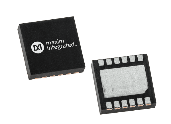
Analog Devices / Maxim Integrated MAX2220x 36V/3.5A Brushed Motor Drivers

Analog Devices Inc. MAX2220x 36V/3.5A Brushed Motor Drivers feature low impedance FETs with a typical 0.3Ω RON that results in high driving efficiency. These brushed motor drivers operate at 36V supply voltage and -40°C to +125°C temperature range. The peak current rating of 3.5A is limited by the Overcurrent Protection (OCP) threshold. This peak current is the maximum current the driver can provide for short transients. ADI MAX2220x motor drivers also feature a non-dissipative and accurate Integrated Current Sensing (ICS) and an embedded internal Current Drive Regulation (CDR) circuit. This motor driver IC is housed in a tiny TDFN12 package with 3mm x 3mm dimensions. Applications include brushed DC motor drives, stepper motor drives (one phase only), and latched valves/solenoids.
Features

  • One full H-Bridge with a 36V voltage rating
  • 300mΩ (typical) total RDS(ON) (high side + low side) (TA = +25°C)
  • Current ratings (+25°C typical)
    • 3.5A IPEAK
    • 2A IRMS
  • Configurable Current Drive Regulation (CDR) for limiting stall and inrush current with Configurable Off Time (tOFF) for CDR
  • Lossless Integrated Current Sensing (ICS) eliminates external bulky resistors and saves power
  • Current Sense Output (CSO) function replica of the internally sensed current is output on the ISEN pin
  • Fault Indicator pin (FAULT)
  • Fully integrated charge pump
  • Protections
    • Overcurrent Protection (OCP) for each individual channel
    • Undervoltage Lockout (UVLO)
    • Thermal Shutdown (TSD) T = 165°C
    • ESD protection 8kV HBM (OUT1 and OUT2 pins)
  • Current Drive Regulation Monitor (CDROUT) (MAX22207 only)
  • Ultra-small TDFN-12 package with 3mm x 3mm dimensions
  • -40°C to +125°C operating temperature range

Applications

  • Brushed DC motor drives
  • Stepper motor drives (one phase only)
  • Latched valves and solenoids

Components

  • The MAX22201 features a user-configurable off time that can be set by connecting an external resistor to the ROFF pin.
  • The MAX22202 features an ENBL/PHASE interface with an additional logic input pin (MODE) to select slow/fast decay. A break condition longer than 2.2ms followed by a high-to-low transition of the MODE pin enters low power sleep mode.
  • The MAX22207 features a CDR monitor open-drain output that is asserted when the internal regulation loop takes control of the driver.
  • The MAX22201 and MAX22207 are controlled with two PWM logic inputs (IN1, IN2), resulting in four possible states: forward, reverse, brake (slow decay), and coast. Setting both inputs low for more than 2.2ms, the MAX22201 enters low-power sleep mode.

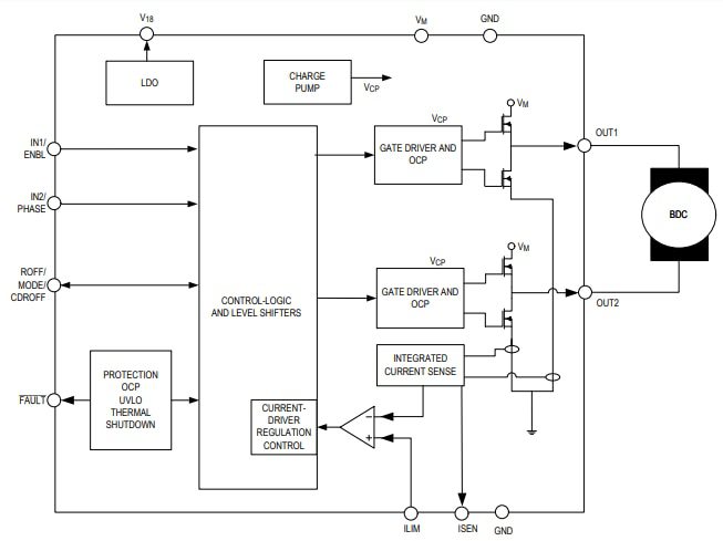
Block Diagram

Block Diagram - Analog Devices / Maxim Integrated MAX2220x 36V/3.5A Brushed Motor Drivers

Analog Devices / Maxim Integrated MAX2220x 36V/3.5A Brushed Motor Drivers