- support@husseinkey.com
- livechat
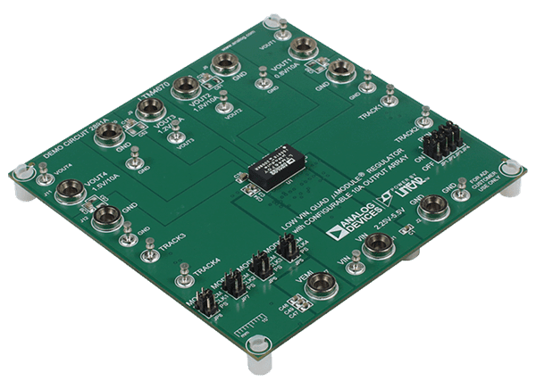
Analog Devices Inc. DC2891A Demonstration Circuit features the LTM®4670EY high-efficiency quad 10A step-down power µModule® regulator. This demo board offers the SSTT pin allowing the user to program output tracking, soft-start period, and die temperature monitoring. The DC2891A demonstration circuit uses the MODE/SYNC pin either to synchronize the switching frequency to an external clock as a clock output or set the PWM mode. The PWM modes of operation are forced continues mode for low noise or pulse-skipping mode for high efficiency at light load. This demo board has optional jumper resistors to parallel multiple LTM4670 channels. For paralleled channels, one channel can be set as master, and the rest can be set as slaves.


