- support@husseinkey.com
- livechat
Analog Devices Inc. ADALM-SR1 (Analog Devices Active Learning Module, Switching Regulator #1) Board is a companion module for a series of Active Learning Lab Exercises covering Buck and Boost regulators. The circuits required for these exercises exceed the complexity that can be constructed on a standard breadboard, so the ADALM-SR1 Board is required to run them.
The Analog Devices Inc. ADALM-SR1 is designed to work in conjunction with the ADALM2000 Advanced Active Learning Module.
The ADALM-SR1 Board is orderable in bundles that include the required additional equipment:
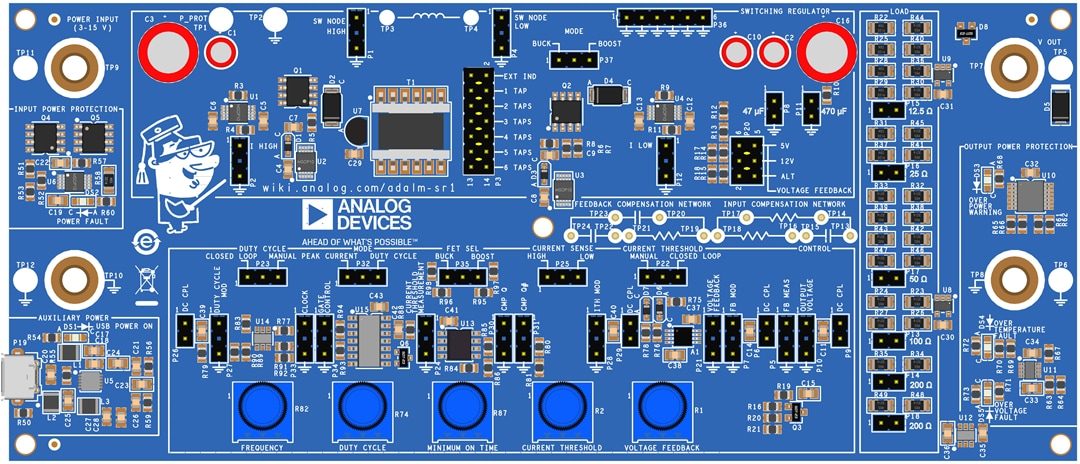
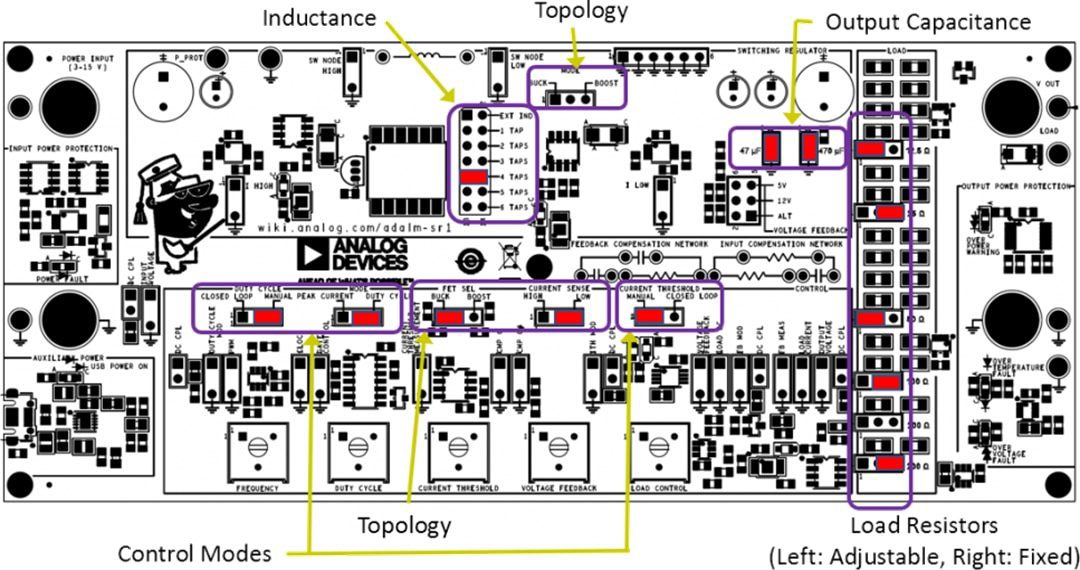

The ADALM-SR1 uses 0.635mm (0.025-mil) headers for configuration jumpers, signal inputs, and signal outputs. Signal inputs and outputs are 2-conductor headers with 5.08mm (200-mil) pitch so that they cannot be confused with configuration jumpers. The lower conductor is always a ground connection (that is not always used), and an arrow indicates whether the upper conductor is an input or output.
The Mode jumper selects between peak current mode and duty cycle control.
An LTC6992 Pulse-Width Modulator allows the switching MOSFET’s duty cycle to be controlled directly, either manually by adjusting the Duty Cycle knob or under the control of the error amplifier. In peak-current control modes, the peak current can be controlled either manually by adjusting the Current Threshold knob or under the control of the error amplifier. The Current Threshold is also always active in voltage control modes, maintaining the per-cycle current limit as an added safety and robustness feature.
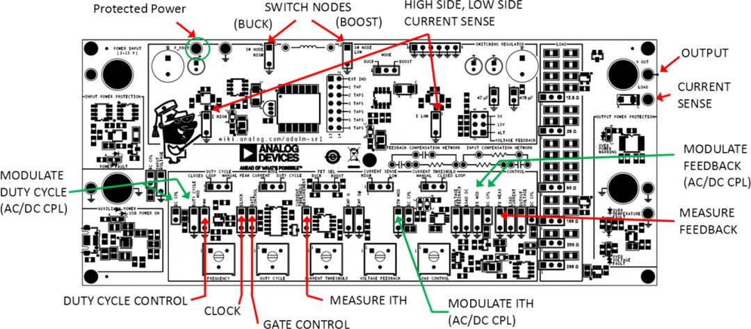

The ADALM-SR1 provides numerous test points for stimulating (modulating) and measuring the operation of the circuit, such as input and output voltage, inductor current, and output current. Several aspects of the circuit’s dynamic response can also be measured:
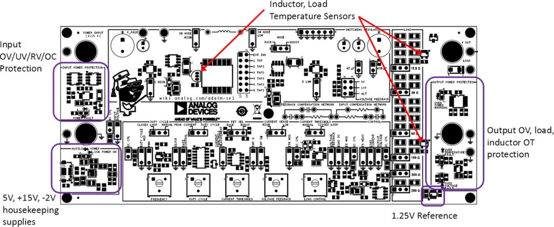

The ADALM-SR1 has two power inputs. The experiment power input is supplied by the user, and the voltage will vary depending on the experiment being run. An additional micro USB connector is the input for a 5V “housekeeping” supply that powers all of the control circuitry, allowing the experiment power to vary over a wide range. An LT3472 boosts/inverts the 5V supply to +15/-2V, respectively. This design provides a high voltage and slightly negative voltage for the LT1995 current sense amplifiers and a negative supply for the error amplifier.
An LT1970-1.25 provides an accurate reference for the error amplifier and duty cycle, current threshold adjustment potentiometers.
The ADALM-SR1 features input overvoltage, undervoltage, reverse voltage, and overcurrent protection. An LTC4368 and associated circuitry protect the experiment power input by only turning on when the supply is between 3V and 15V. The circuit is protected from voltages between -40V and +60V. The LTC4368 also functions as a fuse, shutting off the supply if the current exceeds 2A.
In boost mode, the ADSRALM can produce high voltages under certain conditions. An LTC2912 overvoltage / undervoltage supervisor will disable the switching circuitry if the output exceeds 22V. A SMAJ24A, 24-Volt TVS Diode provides additional protection.


