- support@husseinkey.com
- livechat
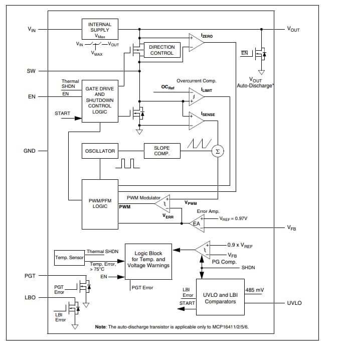
Microchip Technology MCP1641x Low IQ Boost Converters provide an automatic input-to-output voltage bypass operation. This feature optimizes battery utilization and achieves high efficiency while fresh batteries’ nominal voltage is in the same range as the converter’s output value. Microchip MCP1641x Low IQ Boost Converters can be powered by either single-cell, two-cell alkaline/NiMH batteries, or single-cell Li-Ion/Li-Polymer batteries. A low-voltage designed architecture allows the regulator to start up without high inrush current or output voltage overshoot from a low input voltage. The start-up voltage is easily programmed by a resistive divider connected to the UVLO pin. If the resistive divider is not used, the default start-up voltage will be 0.85V. The 0.8V built-in UVLOSTOP helps prevent deep discharge of the alkaline battery, which may cause battery leakage. An open-drain Low Battery Output (LBO) pin will warn the user to replace the battery if the input voltage ramps down to the programmed UVLOSTART value.
The MCP1641x family introduces an additional safety feature to a low-voltage boost converter: overtemperature output. A variety of applications will benefit from combined Power Good and Die Overtemperature (PGT) output, which flags a warning signal when the output voltage level drops by 10% or the die temperature exceeds 75°C, typically. Both functions are implemented in the MCP16411/2/3/4 devices (on the same pin, PGT), while the MCP16415/6/7/8 devices have the Power Good only option.


