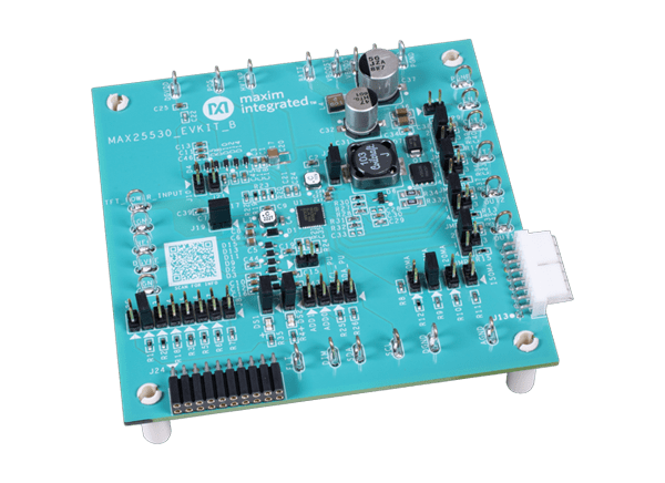
Analog Devices / Maxim Integrated MAX25530 Evaluation Kit

Analog Devices Inc. MAX25530 Evaluation Kit is configured to evaluate the operation of the MAX25530 IC, which is a highly integrated power supply plus LED backlight driver for automotive TFT-LCD applications. The MAX25530 Evaluation Kit is a fully assembled and tested surface-mount PCB that provides a complete power management solution for automotive displays. The Evaluation Kit integrates one buck-boost converter, one boost converter, two gate-voltage controllers, and a boost converter that powers a quad-string LED driver.

ADI MAX25530 Evaluation Kit is able to be configured to operate in a stand-alone mode or an I2C mode. The Evaluation Kit offers an I2C interface that can operate in conjunction with the MINIQUSB+ adapter board or a third-party I2C master. The Kit also includes Windows®-compatible software that provides a simple graphical user interface (GUI) for exercising the IC’s features.
Features

  • Demonstrates robustness of MAX25530
  • 2.8V to 5.5V Input range for TFT power section
  • 4.5V to 42V Input range for LED driver section
  • 2.2MHz or 430kHz I2C programmable boost and inverted buck-boost switching frequency with spread-spectrum option on TFT power section
  • 2.2MHz or 440kHz I2C programmable boost frequency with spread-spectrum option on LED driver section with four 150mA LED drivers
  • TFT Section default output voltages (stand-alone mode)
    • +6V Output at 120mA (step-up switching regulator)
    • -6V Output at 100mA (inverting buck-boost switching regulator)
    • +16V Output at 10mA (positive-charge pump)
    • -7V Output at 10mA (negative-charge pump)
  • HB LED string output currents configurable for 20mA, 50mA, 100mA, 120mA or 150mA
  • Flexible resistor-programmable TFT output sequencing (stand-alone mode)
  • Demonstrates cycle-by-cycle current-limit and thermal-shutdown features on boost LED driver
  • Demonstrates adaptive voltage optimization on LED driver section
  • I2C Programmability
  • Dedicated GUI
  • Proven PCB layout and thermal design
  • Fully assembled and tested

Required Equipment

  • MAX25530 EV kit
  • 2.8 to 5.5V, 2A DC power supply
  • 5V to 36V, 4A DC power supply
  • Two digital voltmeters (DVMs)
  • Four series-connected HB LED strings (6 LEDs each) rated to no less than 150mA
  • Current probe to measure the HB LED current
  • MINIQUSB+ interface board with USB cable
  • Windows-compatible PC with a spare USB port

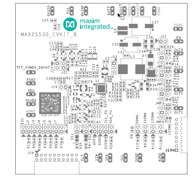
PCB Layout

Analog Devices / Maxim Integrated MAX25530 Evaluation Kit

Analog Devices / Maxim Integrated MAX25530 Evaluation Kit