http://www.ti.com/general/docs/suppproductinfo.tsp?distId=26&gotoUrl=https%3A%2F%2Fwww.ti.com%2Flit%2Fpdf%2Fsnvu783″>View Datasheet

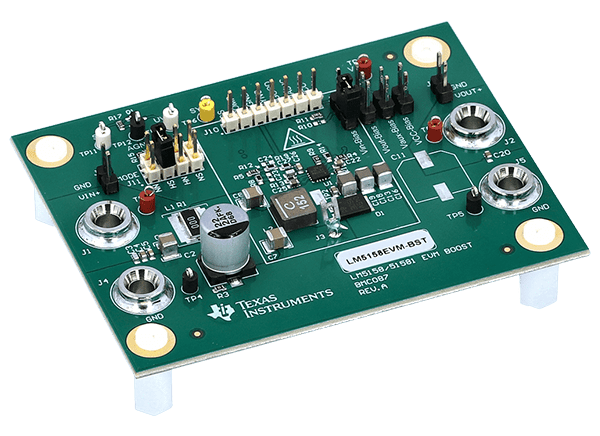
Texas Instruments LM5158EVM-BST Converter Evaluation Module

Texas Instruments LM5158EVM-BST Converter Evaluation Module (EVM) showcases the features and performance of the LM5158 device as a wide input voltage boost converter with a dual random spread spectrum. The standard configuration of the Texas Instruments LM5158EVM-BST is designed to provide a regulated output of 12V at 1.2A from an input of 3V to 9V (load derated to 0.6A from < 6V input), switching at 2.1MHz.
Features

  • A tightly regulated output voltage of 12V with 1% accurate reference voltage
  • High conversion efficiency of > 92% at full load
  • Constant cycle-by-cycle peak inductor current limit over an input voltage range
  • Programmable hiccup mode for output overcurrent protection
  • User-adjustable soft-start time using CSS
  • Output overvoltage protection
  • 2.1MHz switching frequency
  • Multiple BIAS pin and VCC pin connections to test various configurations
    • BIAS connect to VCC
    • BIAS supplied with external power supply
    • BIAS supplied by an output voltage
  • Power-good (PGOOD) indicator with selectable pullup source
  • External clock synchronization
  • Programmable dual random spread spectrum reduces the EMI

Required Equipment

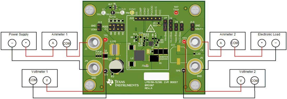
  • Power Supply
    • The input voltage source (VIN) should be a variable supply capable of 0V to 10V and source at least 10A
  • Multimeters
    • Voltmeter 1
      • Input voltage connects from VIN+ to VIN–
    • Voltmeter 2
      • Output voltage connects from VOUT+ to GND
    • Ammeter 1
      • Input current that must be able to handle 10A (a shunt resistor can be used as needed)
    • Ammeter 2
      • Output current that must be able to handle 2A (a shunt resistor can be used as needed)
  • Electronic Load
    • The load should be constant resistance (CR) or constant current (CC) capable
    • It should safely handle 2A at 12V
  • Oscilloscope
    • 20MHz bandwidth and AC coupling
    • Measure the output voltage ripple directly across an output capacitor with a short ground lead
    • It is not recommended to use a long-leaded ground connection due to the possibility of noise being coupled into the signal
    • To measure other waveforms, adjust the oscilloscope as needed

Test Setup

Mechanical Drawing - Texas Instruments LM5158EVM-BST Converter Evaluation Module

Texas Instruments LM5158EVM-BST Converter Evaluation Module