http://www.ti.com/general/docs/suppproductinfo.tsp?distId=26&gotoUrl=https%3A%2F%2Fwww.ti.com%2Flit%2Fpdf%2Fsnvu768″>View Datasheet

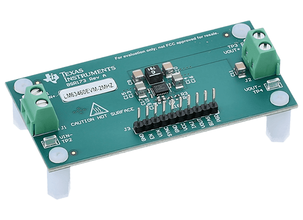
Texas Instruments LM63460EVM-2MHZ/LM64460EVM-2MHZ Converter EVMs

Texas Instruments LM63460EVM-2MHZ/LM64460EVM-2MHZ Converter Evaluation Modules (EVMs) are designed to showcase the performance of the LM63460-Q1 or LM64460-Q1 high-performance, automotive synchronous buck DC/DC converters. Each evaluation module operates over a wide input voltage range of 5.5V to 36V to deliver a fixed 5V output with better than 1% setpoint accuracy and up to 6A output current. Several features to ensure the regulator’s protection during fault conditions include undervoltage lockout (UVLO), internal soft-start, hiccup-mode overcurrent protection (OCP), an open-drain PGOOD indicator, and thermal shutdown. Spread-spectrum frequency modulation is provided by default with the LM63460-Q1. The spread spectrum is configurable in the LM64460-Q1 by connecting the MODE/SYNC pin of the IC to VCC or GND to enable spread spectrum in FPWM and auto modes, respectively. In addition, the Texas Instruments LM63460-Q1 has resistor-adjustable switching frequency and SYNC IN functionality to adjust the frequency to that of an external clock signal.
Features

  • Wide input voltage range of 5.5V to 36V
  • 5V default output voltage with 1% setpoint accuracy
  • Rated for 6A of load current at a switching frequency of 2.1MHz
  • Ultra-low IQ is ideal for automotive off-battery applications
  • Input EMI filter included for CISPR 25 Class 5 conducted emissions
  • Fully assembled, tested, and proven PCB layout with a small solution footprint

Required Equipment

  • Voltage source
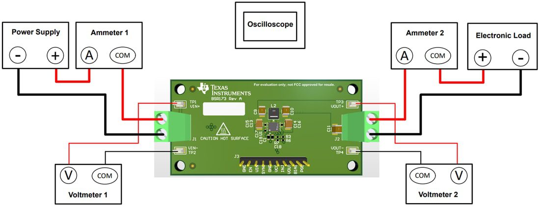
    • The input voltage source VIN should be a 36V variable DC source capable of supplying 6A
  • Multimeters
    • Voltmeter 1
      • Measure the input voltage at VIN+ to VIN–
    • Voltmeter 2
      • Measure the output voltage at VOUT+ to VOUT–
    • Ammeter 1
      • Measure the input current
      • Set the ammeter to a 1-second aperture time
    • Ammeter 2
      • Measure the output current
    • Set the ammeter to a 1-second aperture time
  • Electronic load
    • Use an electronic load set to constant-resistance (CR) or constant-current (CC) mode and capable of 0 ADC to 6 ADC
    • For a no-load input current measurement, disconnect the electronic load as it can draw a small residual current
  • Oscilloscope
    • With the scope set to 20MHz bandwidth and AC coupling, measure the output voltage ripple directly across an output capacitor with a short ground lead normally provided with the scope probe
    • Place the oscilloscope probe tip on the positive terminal of the output capacitor, holding the ground barrel of the probe through the ground lead to the negative terminal of the capacitor
    • TI does not recommend using a long-leaded ground connection because this can induce additional noise given a large ground loop
    • To measure other waveforms, adjust the oscilloscope as needed

Test Setup

Mechanical Drawing - Texas Instruments LM63460EVM-2MHZ/LM64460EVM-2MHZ Converter EVMs

Texas Instruments LM63460EVM-2MHZ/LM64460EVM-2MHZ Converter EVMs